Fresh Breeze
HANDBOOK
RESPECT
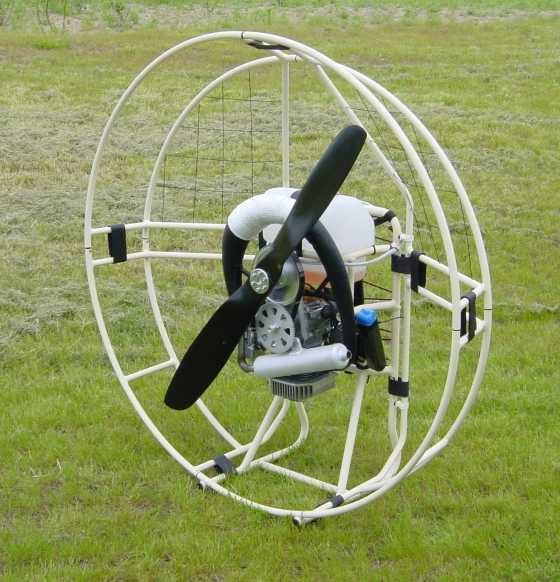
AIRBOSS
Version of Juli 2001.
 |
||
|
ASSEMBLY
|
OPERATION
|
SERVICING |
|
|||||||||
|
||
|
ASSEMBLY
|
OPERATION
|
SERVICING |
|
||||||||||||||||||||||||||||||||||||||||||
|
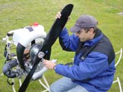
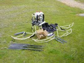
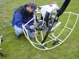
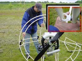
ASSEMBLY THE PARAMOTOR - RESPECT
|
|
ASSEMBLY THE PARAMOTOR - AIRBOSS
|
OPERATIONAL SPECIFICATIONS
IMPORTANT INFORMATION:
|
|||||||||||||||||||||||||||||||||||||||||||||||||||||||||||||||
| Mileage | ca. 3L / hour |
| Flight Duration | up to 3 hours |
| RPM | 0 - 6000 |
| Thrust | up to 60 kp |
| Climbrate | up to 2m / sec |
| Throttle little power | low consumption | |
| Throttle high power | low consumption | |
| Low flight | low consumption | |
| High flight | high consumption | |
| Small chute | high consumption | higher speed |
| Large chute | low consumption | slower speed |
| Light weight pilot | low consumption | slower speed |
| Heavy weight pilot | high consumption | higher speed |
| 06 |
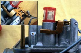
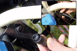
FUEL AND OIL SYSTEM
|
||||||
|
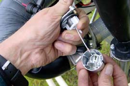
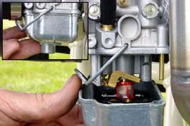
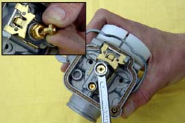
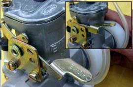
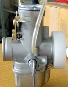
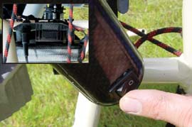
CABURETTOR AND INTAKE SILENCER
|
||||
|
CABURETTOR AND INTAKE SILENCER (2)
|
||||||
|
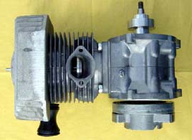
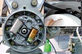
ENGINE
|
||||
|
ENGINE
|
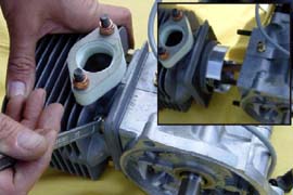
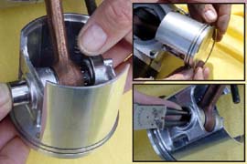
The re-fitting has to be done in reverse order. The piston has an
arrow at the bottom, wich points towards the vent. When the
cylinder is being pushed over the piston, it has to be pressed
together via a clamp.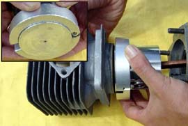 |
|
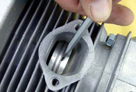
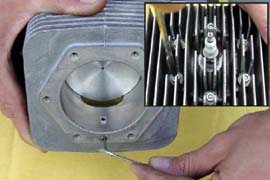
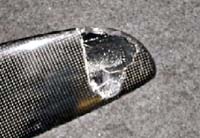
There is a pear shaped depression in the running groove. This
should be scraped clean with an appropriate tool. Afterwards drill
the canal free with an 4mm drill.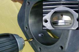 |
|
|
|
| 11 |
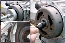
ENGINE
|
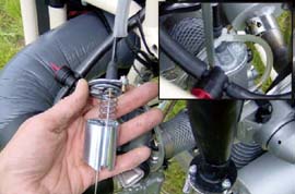
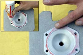
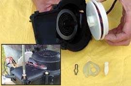
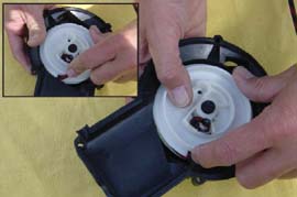
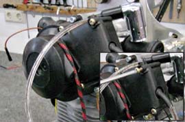
This picture exhibits one of the two sealing-rings of the crankshaft,
which can wear out some time of usage. This can be noticed when
the engine running poorly. For example, the engine is only running
correctly when the choke is pressed. The sealing-rings can be
leverd out from outside.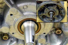 |
|
The starter-rope can now be pulled out of the disc.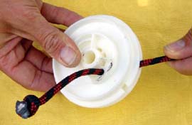 |
|
|
|
| 12 |
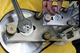
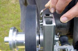
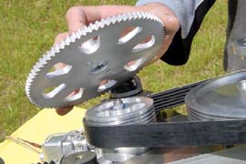
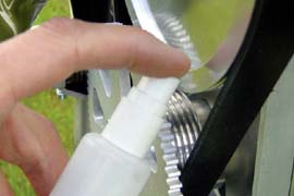
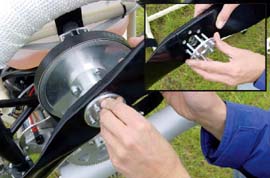
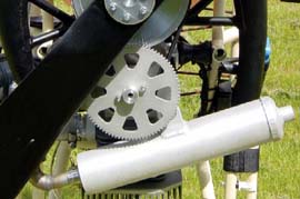
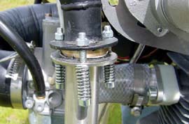
REDUCTION DRIVE SYSTEM
|
||||
|
REDUCTION DRIVE SYSTEM
|
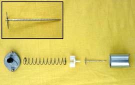
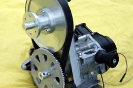
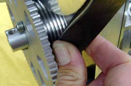
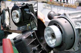
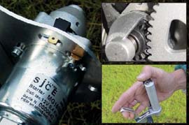
| How to replace the belt? 1. Remove security pin. 2. Loosen central-screw. 3. Loosen belt with tension-screw. 4. Screw in the piston-block into the spark-plug-hole. 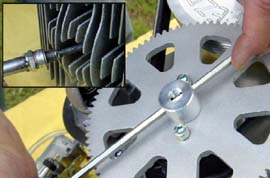 |
|
| 6. Take off belt. 7. Place the new belt onto the pulley. The re-fitting happens in the reverse order. 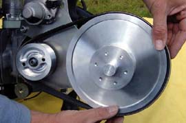 |
|
|
|
| 14 |
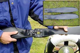
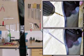
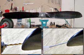
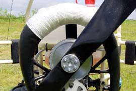
PROPELLER
|
|||||||
|
ELECTRIC
|
|||||||||||||||||||||||||
|
|||||||||||||||||||||||||
POWER IGNITION SYSTEM
|
||||
|
ELECTRIC STARTER
|
||||
|
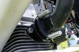
EXHAUST AND SILENCER
|
||||
|
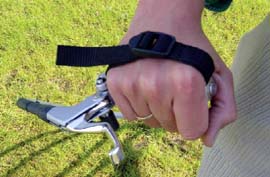
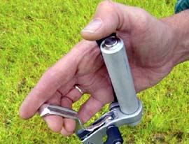
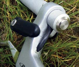
THROTTLE - RESPECT
|
||||
|
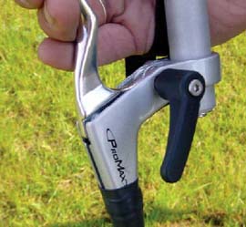
THROTTLE - AIRBOSS
|
||||
|
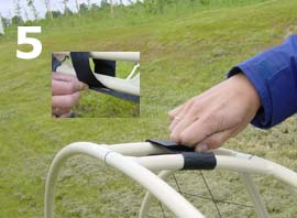
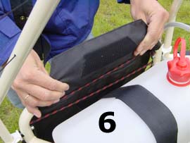
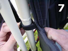
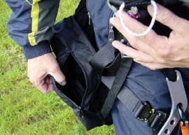
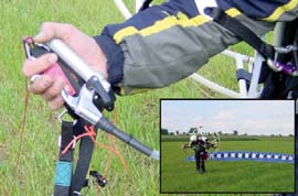
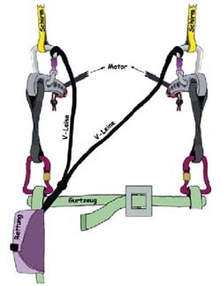
HARNESS AND SUSPENSION
|
||||
|
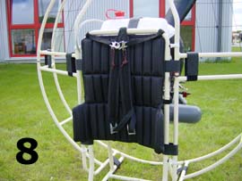
HARNESS AND SUSPENSION
|
|
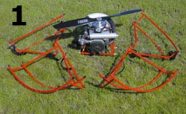
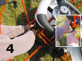
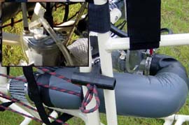
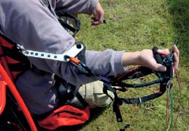
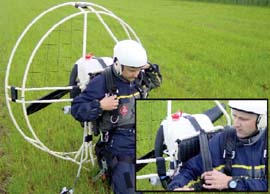
Now one kneels in fornt of the engine and pulls the carrying straps
over the shoulders.
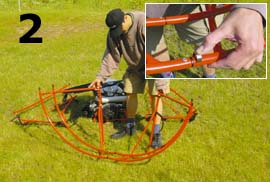
Now one gets up with the whole engine and goes to the chute.
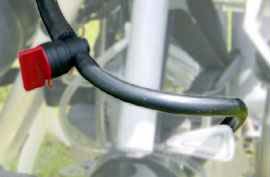
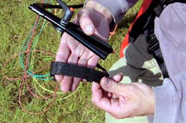
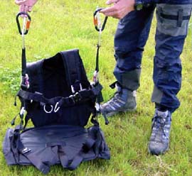
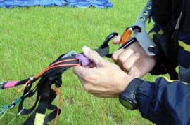
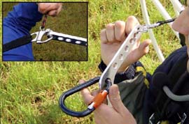
The chute will then be hang into the springlocks for the pilot suspension. |
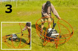
Thereafter the pilot suspension has to be hang into the dropping
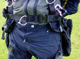
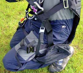
device of the engine. Usually the hind most hole is used for this.
The dropping device should be activated at pending danger, for
example at a water landing, fire at high altitude or a tree touchdown.
The activation occurs when the two strings of the dropping
device are pulled outwards. Because the engine is now not
hanging over the suspension of the chute anymore, the pilot will
be in a brought into a strong reclining position. Thus the engine
can now slide easily over the shoulders. The landing proceeds
from now on without the engine.
|
|
| 23 |
PREFLIGHT CHECK
|
|||||||||||||||||||||||||||||||||||||||||
|
|||||||||||||||||||||||||||||||||||||||||