MANUAL
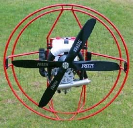
MONSTER
Version February 2003.
 |
||
|
ASSEMBLY
|
OPERATION
|
MAINTENANCE
|
MANUALMONSTERVersion February 2003.
|
||||||
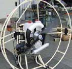
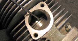
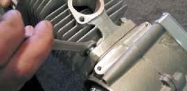
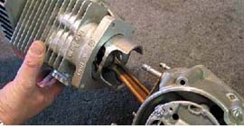
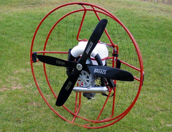
ASSEMBLY OF THE MOTOR
|
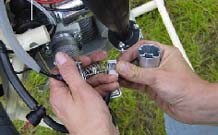
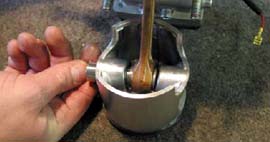
ASSEMBLY OF THE MOTOR (2)
|
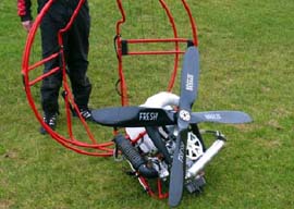
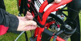
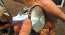
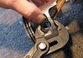
ASSEMBLY OF THE MOTOR (3)
|
TECHNICAL DATES
NEXT DATES ARE DEPEND FROM: WEATHER, ALTITUDE, PILOTS WEIGHT, GLIDER AND SIZE AS WELL AS ATMOSPHERIC HUMITY.
|
| Little throttle | less consumtion | |
| Big throttle | high consumtion | |
| Low flightlevel | less consumtion | |
| High flightlevel | high consumtion | |
| Small glider | high consumtion | high speed |
| Big glider | less consumtion | slow speed |
| Leightweight pilot | less consumtion | slow speed |
| Heavyweight pilot | high consumtion | high speed |
| 06 |
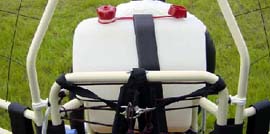
FUEL AND OIL
|
|||||
|
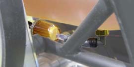
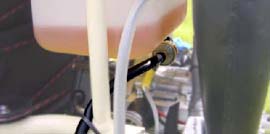
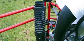
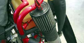
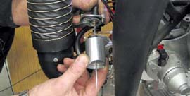
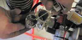
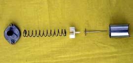
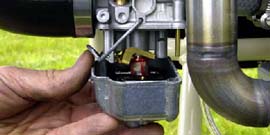
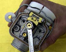
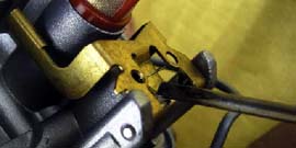
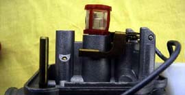
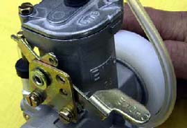
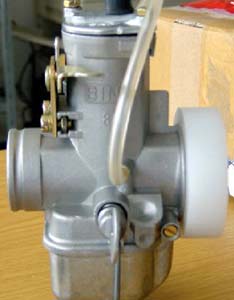
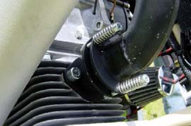
CARBURETTOR AND INTAKESILENCER
|
||||||||
|
CARBURETTOR AND INTAKESILENCER (2)
|
||||
|
CARBURETTOR AND INTAKESILENCER (3)
|
|||||||||
|
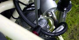
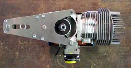
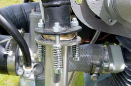
ENGINE
|
||||||||
|
ENGINE (2)
|
||||||||
|
ENGINE (3)
|
||||||||
|
PULLSTARTER
|
||||||||
|
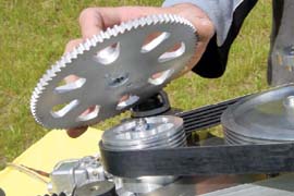
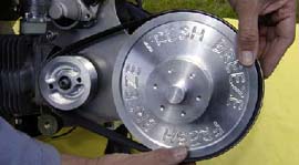
GEARBOX
|
||||||||
|
GEARBOX (2)
|
||||||||
|
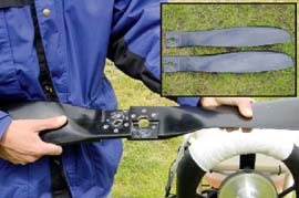
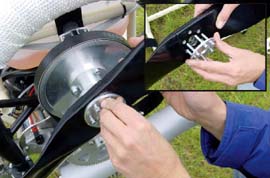
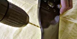
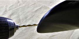
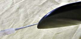
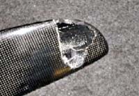
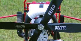
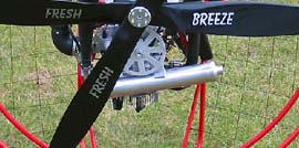
PROPELLER
|
||||||||
|
PROPELLER (2)
|
|||||||
|
ELECTRIC
|
|
|
POWER IGNITION SYSTEM
|
||||||||
|
E-STARTER
|
||||||||
|
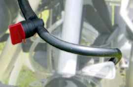
EXHAUST
|
||||||||
|
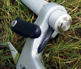
THROTTLE RESPECT
|
||||||||
|
THROTTLE AIRBOSS
|
||||||||
|
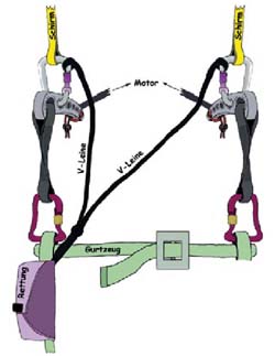
HARNESS
|
||||||||
|
HARNESS (2)
|
||||
|
HARNESS (3)
|
|||||||
|
CHECKLIST
|
|||
|
CHECKLIST (2)
|
|
|
|
|
|
|