MANUAL
SIMONINI
Version February 2003.
 |
||
|
ASSEMBLY
|
OPERATION
|
MAINTENANCE
|
MANUALSIMONINIVersion February 2003.
|
||||||
|
||||||||||||||||||||||||||||||||||
|
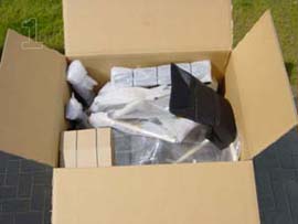
ASSEMBLY OF THE MOTOR
|
| 03 |
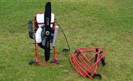
ASSEMBLY OF THE MOTOR (2)
|
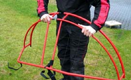
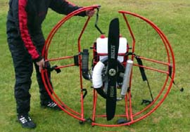
ASSEMBLY OF THE MOTOR (3)
|
TECHNICAL DATES
NEXT DATES ARE DEPEND FROM: WEATHER, ALTITUDE, PILOTS WEIGHT, GLIDER AND SIZE AS WELL AS ATMOSPHERIC HUMITY.
|
| Little throttle | less consumtion | |
| Big throttle | high consumtion | |
| Low flightlevel | less consumtion | |
| High flightlevel | high consumtion | |
| Small glider | high consumtion | high speed |
| Big glider | less consumtion | slow speed |
| Leightweight pilot | less consumtion | slow speed |
| Heavyweight pilot | high consumtion | high speed |
| 06 |
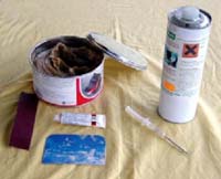
FUEL AND OIL
|
|||||
|
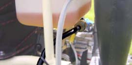
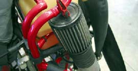
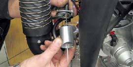
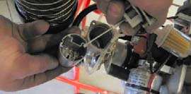
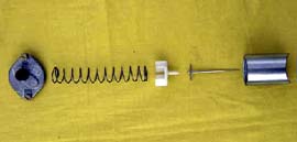
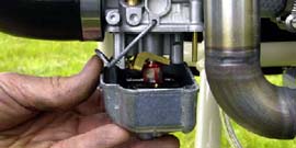
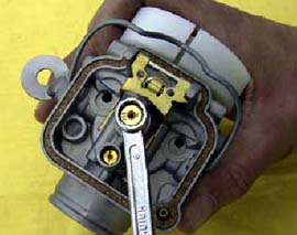
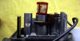
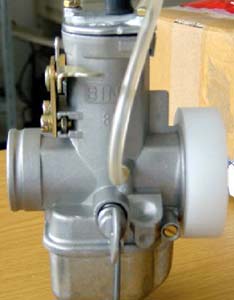
CARBURETTOR AND INTAKESILENCER
|
||||||||
|
CARBURETTOR AND INTAKESILENCER (2)
|
||||
|
CARBURETTOR AND INTAKESILENCER (3)
|
|||||||||
|
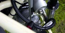
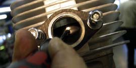
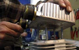
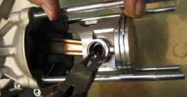
ENGINE
|
||||||||
|
ENGINE (2)
|
||||||||
|
ENGINE (3)
|
||||||||
|
GEARBOX
|
||||||||
|
||||||||
GEARBOX (2)
|
||||||
|
PROPELLER
|
||||||||
|
PROPELLER (2)
|
|||||||
|
POWER IGNITION SYSTEM
|
||||||||
|
||||||||
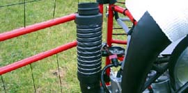
EXHAUST
|
||||||||
|
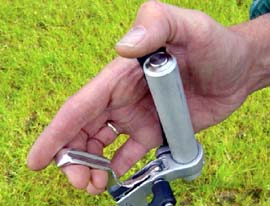
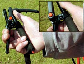
THROTTLE RESPECT
|
||||||||
|
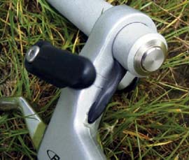
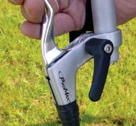
THROTTLE AIRBOSS
|
||||||||
|
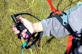
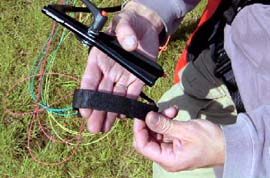
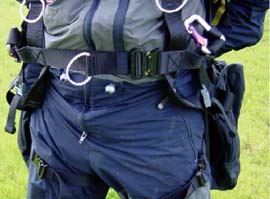
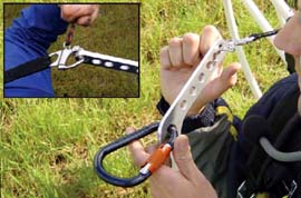
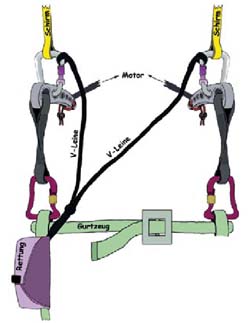
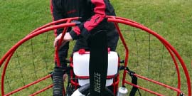
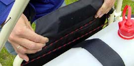
HARNESS
|
||||||||
|
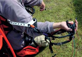
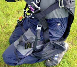
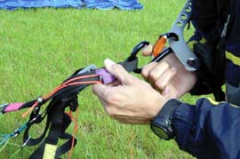
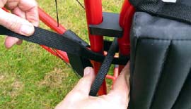
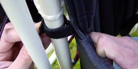
HARNESS (2)
|
||||
|
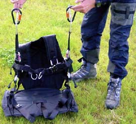
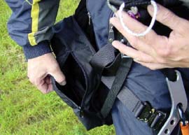
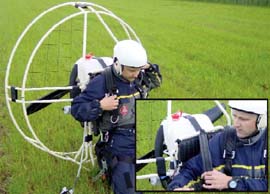
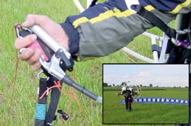
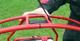
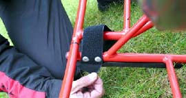
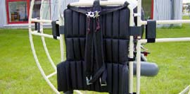
HARNESS (3)
|
|||||||
|
CHECKLIST
|
||
|
CHECKLIST (2)
|
||
|
|
|
|
|
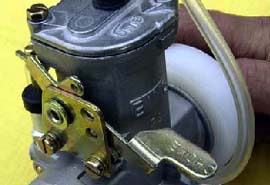
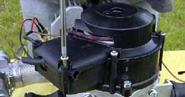
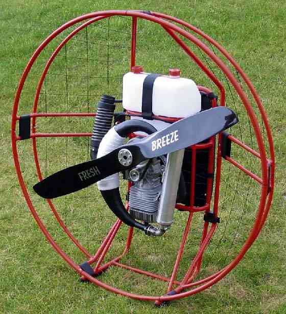
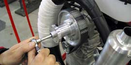
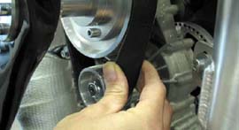
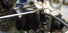
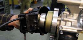
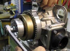
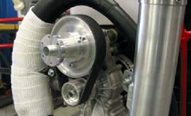 The power-transmission of the gears happens via a Poly V Belt (730
8 PK). The transmission ratio equals 1 : 2,64. The number of the revolution at full load equals 2200 rpm. The lifespan of the belt is aprox.
50-100 hrs. Too little tension shorthens the belt lifspan drastically.
The power-transmission of the gears happens via a Poly V Belt (730
8 PK). The transmission ratio equals 1 : 2,64. The number of the revolution at full load equals 2200 rpm. The lifespan of the belt is aprox.
50-100 hrs. Too little tension shorthens the belt lifspan drastically.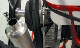
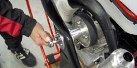
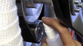
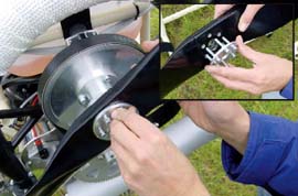

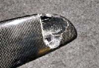
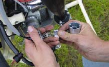
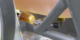
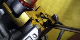
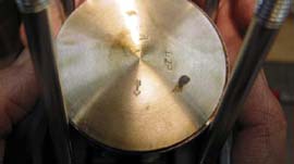
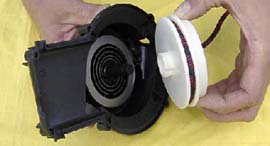
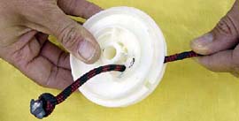
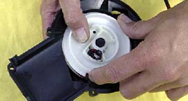
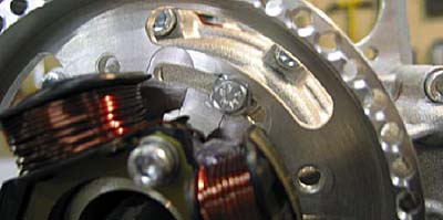 To find the right position of point of ignition look to these picture.